Years of production: 2010
2011
2012
2013
2014
2015
2016
2017
2018
2019
Power Distribution Box - fuse box diagram
The power distribution box is in the engine compartment. It has high-current fuses that protect the vehicle's main electrical systems from overloads.
If you disconnect and reconnect the battery, you will need to reset some features.
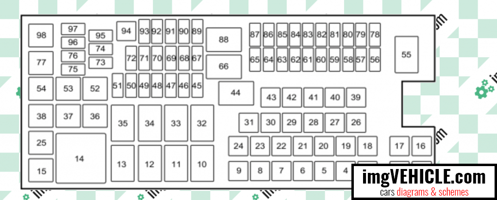
| Fuse Location | Fuse Rating | Protected Component |
|---|
| 1 | - | Not used. |
| 2 | - | Not used. |
| 3 | - | Not used. |
| 4 | 30A 1 | Wiper motor relay. |
| 5 | 50A 1 | Anti-lock brake system pump. |
| 6 | - | Not used. |
| 7 | - | Not used. |
| 8 | 20A 1 | Moonroof. Power sunshade. |
| 9 | 20A 1 | Second row power point. |
| 10 | - | Not used. |
| 11 | Relay | Heated rear window relay. |
| 12 | - | Not used. |
| 13 | Relay | Starter motor relay. |
| 14 | Relay | Left-hand cooling fan number 2 relay. |
| 15 | Relay | Fuel pump relay. |
| 16 | - | Not used. |
| 17 | - | Not used. |
| 18 | 40A 1 | Front blower motor relay. |
| 19 | 30A 1 | Starter relay. |
| 20 | 20A 1 | Storage bin power point. |
| 21 | 20A 1 | Rear heated seat module. |
| 22 | - | Not used. |
| 23 | 30A 1 | Driver power seat. Memory module. |
| 24 | - | Not used. |
| 25 | - | Not used. |
| 26 | 40A 1 | Heated rear window relay. |
| 27 | 20A 1 | Cigar lighter. |
| 28 | 30A 1 | Climate controlled seats. |
| 29 | 40A 1 | Electric fan relay 1. |
| 30 | 40A 1 | Electric fan relay 2. |
| 31 | 25A 1 | Electric fan relay 3. |
| 32 | Relay | Massage control seat relay. |
| 33 | Relay | Right-hand cooling fan relay. |
| 34 | Relay | Blower motor relay. |
| 35 | Relay | Left-hand cooling fan Number 1 relay. |
| 36 | - | Not used. |
| 37 | - | Not used. |
| 38 | - | Not used. |
| 39 | - | Not used. |
| 40 | - | Not used. |
| 41 | - | Not used. |
| 42 | 30A 2 | Passenger power seat. |
| 43 | 20A 1 | Anti-lock brake system valves. |
| 44 | - | Not used. |
| 45 | 5A 2 | Rain sensor. |
| 46 | - | Not used. |
| 47 | - | Not used. |
| 48 | - | Not used. |
| 49 | - | Not used. |
| 50 | 15A 2 | Heated mirrors. |
| 51 | - | Not used. |
| 52 | - | Not used. |
| 53 | - | Not used. |
| 54 | - | Not used. |
| 55 | Relay | Wiper relay. |
| 56 | - | Not used. |
| 57 | 20A 2 | Left-hand high intensity discharge headlamp. |
| 58 | 10A 2 | Alternator A-line. |
| 59 | 10A 2 | Brake on/off switch. |
| 60 | - | Not used. |
| 61 | - | Not used. |
| 62 | 10A 2 | A/C clutch relay. |
| 63 | - | Not used. |
| 64 | 15A 2 | Massage control seats. |
| 65 | 30A 2 | Fuel pump relay. Fuel injectors. |
| 66 | Relay | Powertrain control module relay. |
| 67 | 20A 2 | Oxygen sensor heater. Mass airflow sensor. Variable camshaft timing solenoid valve. Canister vent solenoid. Canister purge solenoid. |
| 68 | 20A 2 | Ignition coils. |
| 69 | 20A 2 | Vehicle power 1 (powertrain control module). |
| 70 | 15A 2 | A/C clutch. Fan control relay coils 1-3. Variable air conditioning compressor. Auxiliary transmission warmup. Turbo charge waste-gate control. Electronic compressor bypass valve. All-wheel drive module. Positive crankcase ventilation heater. |
| 71 | - | Not used. |
| 72 | - | Not used. |
| 73 | - | Not used. |
| 74 | - | Not used. |
| 75 | - | Not used. |
| 76 | - | Not used. |
| 77 | - | Not used. |
| 78 | 20A 2 | Right high-intensity discharge headlamp. |
| 79 | - | Not used. |
| 80 | - | Not used. |
| 81 | - | Not used. |
| 82 | - | Not used. |
| 83 | - | Not used. |
| 84 | - | Not used. |
| 85 | - | Not used. |
| 86 | 7.5A 2 | Powertrain control module. Keep alive power and relay. Canister vent solenoid. |
| 87 | 5A 2 | Run/start relay. |
| 88 | Relay | Run/start relay. |
| 89 | 5A2 | Front blower relay coil. Electrical power assist steering module. |
| 90 | 10A 2 | Powertrain control module run/start. |
| 91 | 10A 2 | Adaptive cruise control module. |
| 92 | 10A 2 | Anti-lock brake system module. |
| 93 | 5A 2 | Rear window defrost relay. |
| 94 | 30A 1 | Passenger compartment fuse panel run/start. |
| 95 | - | Not used. |
| 96 | - | Not used. |
| 97 | - | Not used. |
| 98 | Relay | A/C clutch relay. |
1 - J-case fuses.
2 - Mini fuses.
Passenger Compartment Fuse Panel - fuse box diagram
The fuse panel is under the instrument panel to the left of the steering wheel. You may need to remove a trim panel to access it.
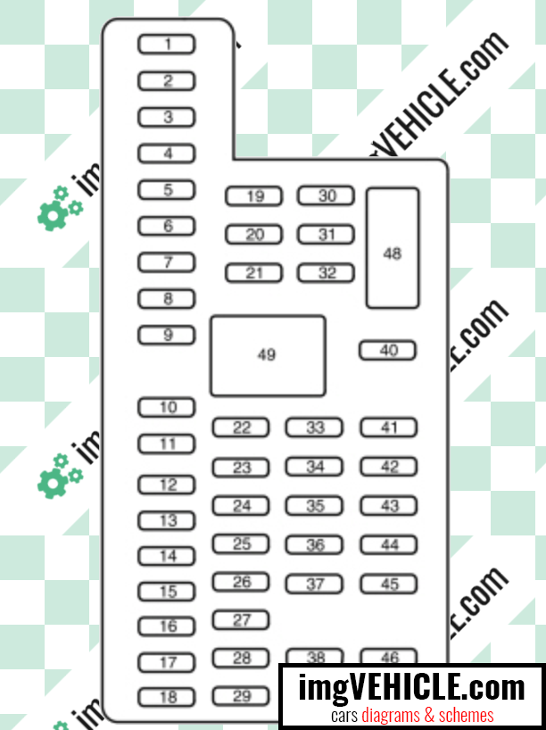
| Fuse Location | Fuse Rating | Protected Component |
|---|
| 1 | 30A | Left front and right rear smart window motors. |
| 2 | 15A | Driver seat switch. |
| 3 | 30A | Right front smart window motor. |
| 4 | 10A | Demand lamps battery saver relay. |
| 5 | 20A | Audio amplifier. |
| 6 | 5A | Not used (spare). |
| 7 | 7.5A | Driver seat module logic. Left front door zone module. Keypad. |
| 8 | 10A | Not used (spare). |
| 9 | 10A | SYNC module. Multi-function displays. Electronic finish panel. Radio frequency transceiver module. |
| 10 | 10A | Run accessory relay. |
| 11 | 10A | Intelligent access module logic. Heads-up display. |
| 12 | 15A | Puddle lamp. Backlighting LED. Interior lighting. |
| 13 | 15A | Right-hand direction indicators. |
| 14 | 15A | Left-hand direction indicators. |
| 15 | 15A | Stop lamp. Backup lamp. |
| 16 | 10A | Right low beam. |
| 17 | 10A | Left low beam. |
| 18 | 10A | Start button. Keypad illumination. Brake-shift interlock. Powertrain control module wake-up. Immobilizer transceiver module. |
| 19 | 20A | Audio amplifiers. |
| 20 | 20A | All lock motor relay and coil. Driver lock motor relay and coil. |
| 21 | 10A | Extended power module. |
| 22 | 20A | Horn relay. |
| 23 | 15A | Steering wheel control module logic Instrument cluster. |
| 24 | 15A | Steering wheel control module. Datalink. |
| 25 | 15A | Decklid release. |
| 26 | 5A | Ignition switch. Push button ignition switch. |
| 27 | 20A | Intelligent access module power. |
| 28 | 15A | Not used (spare). |
| 29 | 20A | Radio. Global positioning system module. |
| 30 | 15A | Front park lamps. |
| 31 | 5A | Not used (spare). |
| 32 | 15A | Smart window motors. Master window and mirror switch. Rear window power sunshade module. Lock switch illumination. |
| 33 | 10A | Not used (spare). |
| 34 | 10A | Reverse park aid module. Automatic high beam and lane departure module. Rear heated seat module. Blind spot monitor module. Rear video camera. |
| 35 | 5A | Motorized humidity sensor. Heads-up display. Traction control switch. |
| 36 | 10A | Heated steering wheel. |
| 37 | 10A | Not used (spare). |
| 38 | 10A | Auto–dimming mirror (without automatic high beam and lane departure module). Moonroof module and switch. |
| 39 | 15A | High beams. |
| 40 | 10A | Rear park lamps. |
| 41 | 7.5A | Extended power module. |
| 42 | 5A | Not used (spare). |
| 43 | 10A | Not used (spare). |
| 44 | 10A | Not used (spare). |
| 45 | 5A | Not used (spare). |
| 46 | 10A | Climate control module. |
| 47 | 15A | Not used (spare). |
| 48 | 30A Circuit breaker | Front passenger power window. Rear power windows. |
| 49 | Relay | Delayed accessory. |
All Ford Taurus VI info & diagrams provided on this site are provided for general information purpose only. Actual Ford Taurus VI (2010-2019) diagrams & schemes (fuse box diagrams & layouts, location diagrams, wiring diagrams etc.) may vary depend on the model version.