Years of production: 2012
2013
2014
2015
2016
2017
2018
2019
2020
Power Distribution Box fuses
The power distribution box of the Ford Fusion II is in the engine compartment. It has high-current fuses that protect your vehicle's main electrical systems from overloads.
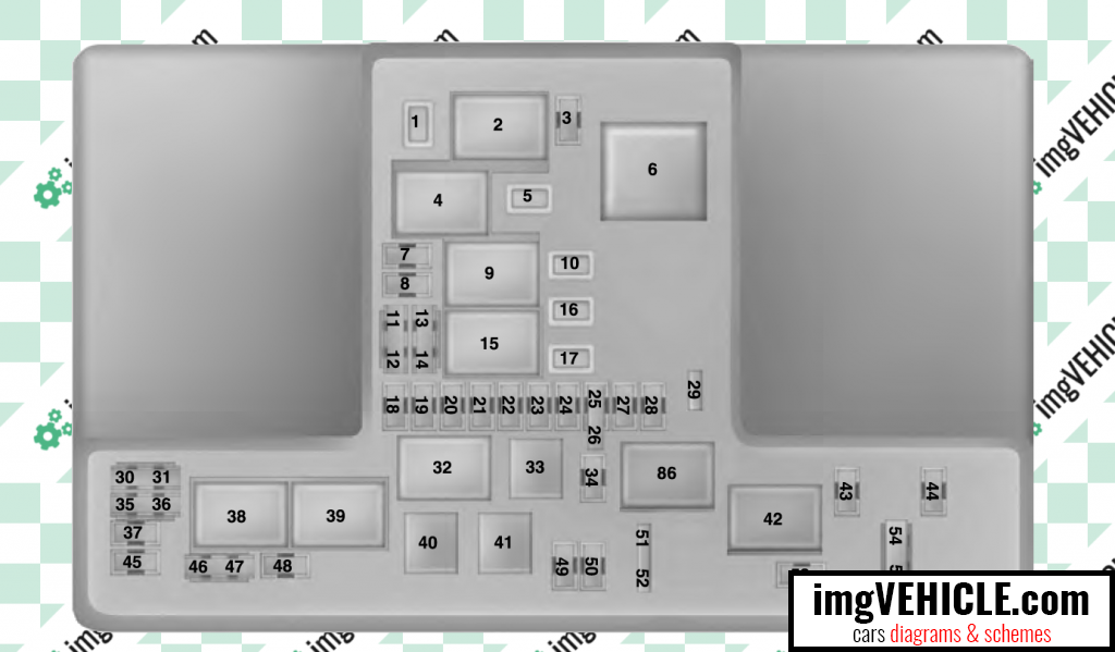
| Fuse or Relay Number | Fuse Rating | Protected Component |
|---|
| 1 | 30A(1) | Panoramic moonroof. |
| 2 | - | Starter relay. |
| 3 | 15A(3) | Rain sensor. |
| 4 | - | Blower motor relay. |
| 5 | 20A(1) | Power point 3 - back of console. |
| 6 | - | Not used. |
| 7 | 20A(3) | Powertrain control module - vehicle power 1. Powertrain control module power. |
| 8 | 20A(3) | Powertrain control module - vehicle power 2. Emission components. |
| 9 | - | Powertrain control module relay. |
| 10 | 20A(1) | Power point 1 - driver front. |
| 11 | 15A(2) | Powertrain control module - vehicle power 4. Ignition coils. |
| 12 | 15A(2) | Powertrain control module - vehicle power 3. Non-emission components. |
| 13 | 10A(2) | Not used (spare). |
| 14 | 10A(2) | Not used (spare). |
| 15 | - | Run-start relay. |
| 16 | 20A(1) | Power point 2 - console. |
| 17 | 20A(1) | Not used (spare). |
| 18 | 20A(3) | Not used (spare). |
| 19 | 10A(3) | Run-start electronic power assist steering. |
| 20 | 10A(3) | Adaptive cruise control. |
| 21 | 15A(3) | Run/start transmission control. Transmission oil pump start/stop. |
| 22 | 10A(3) | Air conditioner clutch solenoid. |
| 23 | 15A(3) | Run-start. Blind spot information system. Rear view camera. Heads-up display. Voltage stability module. Gear shift actuator. |
| 24 | - | Not used. |
| 25 | 10A(2) | Run-start anti-lock brake system. |
| 26 | 10A(2) | Run-start powertrain control module. |
| 27 | 10A(3) | Not used (spare). |
| 28 | - | Not used. |
| 29 | 5A(3) | Mass air flow monitor. |
| 30 | - | Not used. |
| 31 | - | Not used. |
| 32 | - | Electric fan 1 relay. |
| 33 | - | A/C clutch relay. |
| 34 | - | Not used. |
| 35 | - | Not used. |
| 36 | - | Not used. |
| 37 | - | Not used. |
| 38 | - | Electric fan 2 relay. |
| 39 | - | Electric fan coil 2 and 3 relay. |
| 40 | - | Horn relay. |
| 41 | - | Not used. |
| 42 | - | Fuel pump coil relay. |
| 43 | - | Not used. |
| 44 | 20A(3) | Left hand side headlamp ballast. |
| 45 | 5A(3) | Not used (spare). |
| 46 | - | Not used. |
| 47 | - | Not used. |
| 48 | - | Not used. |
| 49 | 10A(3) | Not used (spare). |
| 50 | 20A(3) | Horn. |
| 51 | - | Not used. |
| 52 | - | Not used. |
| 53 | 10A(3) | Not used (spare). |
| 54 | 10A(2) | Brake on off switch. |
| 55 | 10A(2) | ALT sensor. |
(1) - Micro 2 fuse.
(2) - Micro 3 fuse.
(3) - M case fuse.
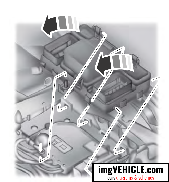
Power Distribution Box - Bottom fuses
There are fuses on the bottom of the fuse
box. To access the bottom of the fuse box,
do the following:
- Release the two latches on both sides
of the fuse box.
- Raise the inboard side of the fuse box
from the cradle.
- Move the fuse box toward the center
of the engine compartment.
- Pivot the outboard side of the fuse box
to access the bottom side.
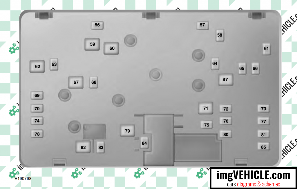
| Fuse or Relay Number | Fuse Rating | Protected Component |
|---|
| 56 | - | Not used. |
| 57 | - | Not used. |
| 58 | 30A(1) | Fuel pump feed. |
| 59 | 30A(2) | Electric fan 3 |
| 60 | 30A(2) | Electric fan 1 (1.5L, 2.0L, and 2.5L engines). |
| 61 | - | Not used. |
| 62 | 50A(2) | Body control module 1. |
| 63 | 25A(1) | Electric fan 2 (1.5L, 2.0L, and 2.5L engines). |
| 64 | 30A(1) | Not used (spare). |
| 65 | 20A(1) | Front heated seat. |
| 66 | 15A(1) | Not used (spare). |
| 67 | 50A(2) | Body control module 2. |
| 68 | 40A(2) | Heated rear window. |
| 69 | 30A(1) | Anti-lock brake system valves. |
| 70 | 30A(1) | Passenger seat. |
| 71 | - | Not used. |
| 72 | 20A(1) | Trans oil pump. |
| 73 | 20A(1) | Rear heated seats. |
| 74 | 30A(1) | Driver seat module. |
| 75 | 25A(1) | Wiper motor 1. |
| 76 | 30A(1) | Not used (spare). |
(1) - M case fuse.
(2) - J case fuse.
Passenger Compartment Fuse Panel
The fuse panel is under the instrument panel to the left of the steering column.
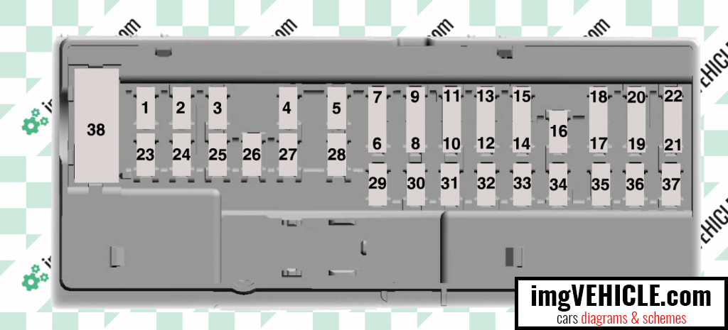
| Fuse or Relay Number | Fuse Rating | Protected Component |
|---|
| 1 | - | Not Used |
| 2 | 7.5A(1) | Lumbar. |
| 3 | 20A(1) | Driver door unlock. |
| 4 | 5A(1) | Not used (spare). |
| 5 | 20A(1) | Subwoofer amplifier. |
| 6 | 10A(2) | Not Used (spare). |
| 7 | 10A(2) | Not used (spare). |
| 8 | 10A(2) | Not used (spare). |
| 9 | 10A(2) | Not used (spare). |
| 10 | 5A(2) | Keypad. Cellphone passport module. |
| 11 | 5A(2) | Not used (spare). |
| 12 | 7.5A(2) | Climate control. Gear shift. |
| 13 | 7.5A(2) | Steering wheel column lock. Cluster. Datalink logic. |
| 14 | 10A(2) | Extended power module. |
| 15 | 10A(2) | Datalink gateway module. |
| 16 | 15A(1) | Child lock. |
| 17 | 5A(2) | Not used (spare). |
| 18 | 5A(2) | Push button stop start switch. |
| 19 | 7.5A(2) | Extended power module. |
| 20 | 7.5A(2) | Adaptive headlamp. |
| 21 | 5A(2) | Humidity and in–car temperature sensor. |
| 22 | 5A(2) | Not used (spare). |
| 23 | 10A(1) | Delayed accessory (power inverter logic, moonroof logic, driver master switch). |
| 24 | 20A(1) | Central lock/unlock. |
| 25 | 30A(1) | Driver door (window, mirror). |
| 26 | 30A(1) | Front passenger door (window, mirror). |
| 27 | 30A(1) | Moonroof. |
| 28 | 20A(1) | Amplifier. |
| 29 | 30A(1) | Rear driver side door (window). |
| 30 | 30A(1) | Rear passenger side door (window). |
| 31 | 15A(1) | Not used (spare). |
| 32 | 10A(1) | Global positioning system. Display. Voice control. Radio frequency receiver. |
| 33 | 20A(1) | Radio. Active noise control. |
| 34 | 30A(1) | Run-start bus (fuse 19, 20, 21, 22, 35, 36, 37, circuit breaker). |
| 35 | 5A(1) | Not used (spare). |
| 36 | 15A(1) | Auto-dimming rear view mirror. Continuous control damping suspension. Rear heated seats. |
| 37 | 20A(1) | Heated steering wheel. |
| 38 | 30A | Not used. |
(1) - Micro 2 fuse.
(2) - Micro 3 fuse.
All Ford Fusion II info & diagrams provided on this site are provided for general information purpose only. Actual Ford Fusion II (2012-2020) diagrams & schemes (fuse box diagrams & layouts, location diagrams, wiring diagrams etc.) may vary depend on the model version.