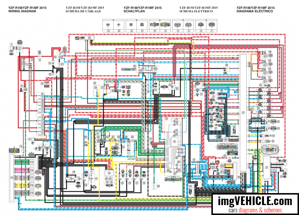
YZF-R1/YZF-R1F 2015
1. ACmagneto
2. Rectifier/regulator
3. Mainswitch
4. Mainfuse
5. Radiatorfanmotorrelay
6. Hazardlightingfuse
7. Fuelinjectionsystemfuse
8. Electricthrottlevalvefuse
9. Backupfuse
10. Radiator fan motor fuse (right)
11. Radiator fan motor fuse (left)
12. Ignition fuse
13. Signaling system fuse
14. ABS ECU fuse
15. ABS solenoid fuse
16. Headlight fuse
17. Auxiliary fuse
18. Joint coupler
19. Battery
20. Engine ground
21. ABS motor fuse
22. Starter relay
23. Starter motor
24. Immobilizer unit
25. Handlebar switch (right)
26. Front brake light switch
27. Wheel switch
28. Start/engine stop switch
29. Relay unit
30. Starting circuit cut-off relay
31. Fuel pump relay
32. Neutral switch
33. Sidestand switch
34. Fuel sender
35. Fuel pump
36. Shift switch
37. ECU (Engine Control Unit)
38. Ignition coil #1
39. Ignition coil #2
40. Ignition coil #3
41. Ignition coil #4
42. Spark plug
43. Air induction system solenoid 44. Primary injector #1
45. Primary injector #2
46. Primary injector #3
47. Primary injector #4
48. Secondary injector #1
49. Secondary injector #2
50. Secondary injector #3
51. Secondary injector #4
52. Accelerator position sensor 53. Throttle position sensor
54. Intake funnel servo motor
55. Throttle servo motor
56. Steering damper solenoid
57. ABS ECU (Electronic Control Unit)
58. Front wheel sensor
59. Rear wheel sensor
60.Jointconnector
61.Yamahadiagnostictoolcou-pler
62. CCU (Communication Control Unit) (OPTION)
63. GPS unit (OPTION)
64. IMU (Inertial Measurement Unit)
65. Intake solenoid
66. EXUP servo motor
67. Coolant temperature sensor
68. Crankshaft position sensor
69. O2 sensor 2 (right side)
70. O2 sensor 1 (left side)
71. Intake air temperature sensor
72. Atmospheric pressure sensor
73. Intake air pressure sensor
74. Cylinder identification sensor
75. Gear position sensor
76. Meter assembly
77. Immobilizer system indicator light
78. Fuel level warning light
79. Neutral indicator light
80. Shift timing indicator light
81. Multi-function meter
82. Stability control indicator light
83. Oil pressure and coolant temperature warning light
84. Engine trouble and system warning light
85. Turn signal indicator light
86. Meter light
87. ABS warning light
88. High beam indicator light
89. Oil pressure switch
90. Rear brake light switch
91. Handlebar switch (left)
92. Mode switch
93. Pass/LAP switch
94. Dimmer switch
95. Horn switch
96. Horn
97. Clutch switch
98. Turn signal switch
99. Hazard switch
100.Rear turn signal light (right)
101.Rear turn signal light (left)
102.Front turn signal light (right)
103.Front turn signal light (left)
104.Headlight control unit
105.Headlight (high beam)
106.Headlight (low beam)
107.Tail/brake light
108.License plate light
109.Auxiliary light
110.Radiator fan motor (right)
111.Radiator fan motor (left)
112.Auxiliary DC outlet
For R1 parts I'd recommend
Yamaha spare parts shop. Online catalog can be found
here