Toyota Camry XV40 (2006-2011) fuse box diagrams & schemes

Years of production: 2006 2007 2008 2009 2010 2011

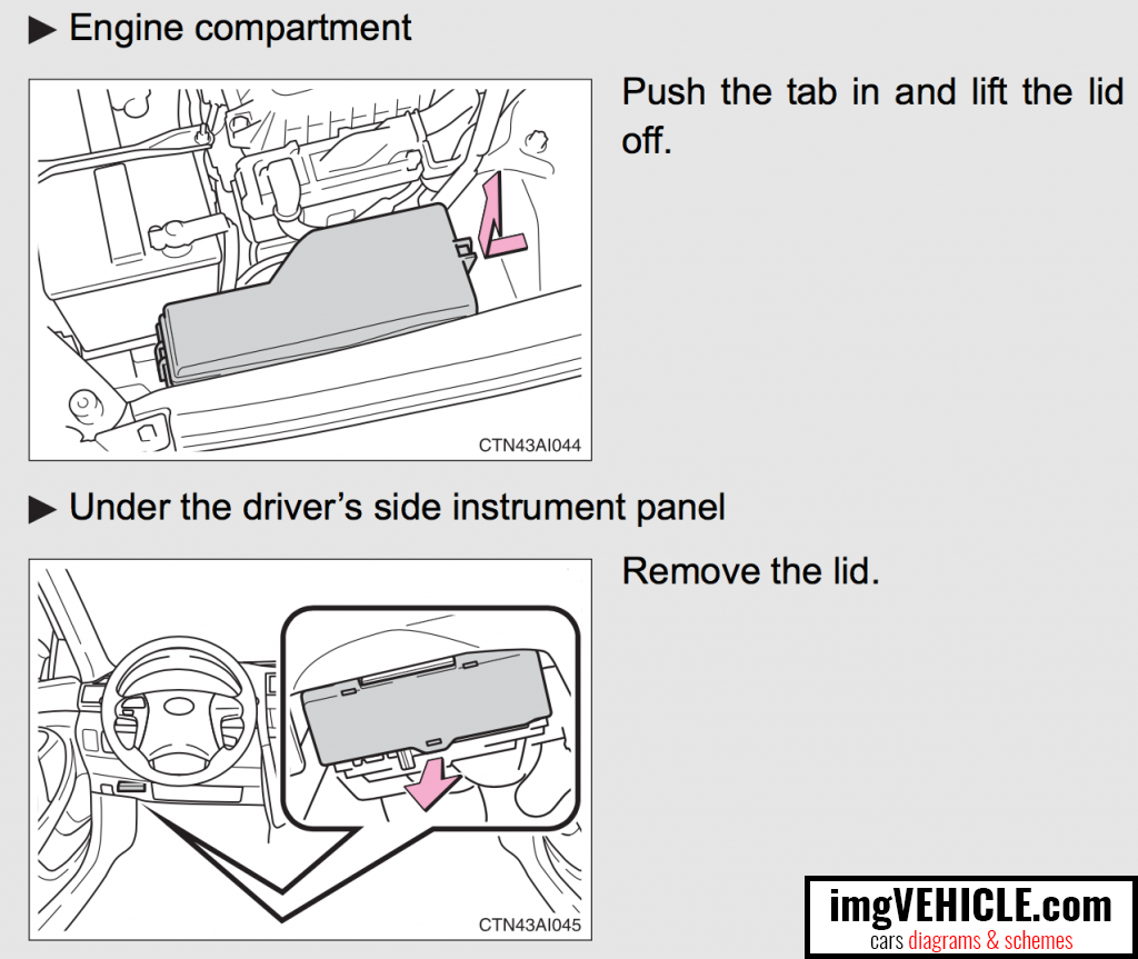
Location

Toyota Camry XV40 Fuse box location

If any of the electrical components do not operate, a fuse may have blown. If this happens, check and replace the fuses as necessary.1) Vehicles with smart key system: Turn the “ENGINE START STOP” switch OFF. Vehicles without smart key system: Turn the engine switch OFF.2)Open the fuse box cover.

Engine compartment diagram

Toyota Camry XV40 Fuse box engine compartment diagram
FuseAmpereCircuit
1SPARE30 ASpare fuse
2SPARE15 ASpare fuse
3SPARE10 ASpare fuse
4RR FOG10 ANo circuit
5FR DEF15 ANo circuit
6AM27.5 AStarting system
7ALT-S7.5 ACharging system
8MAYDAY/TEL7.5 ANo circuit
9E-ACM10 ANo circuit
10ETCS10 AElectronic throttle control system
11HAZ15 ATurn signal lights
12IG220 AMultiport fuel injection system/ sequential multiport fuel injection system; starting system; GAUGE NO.2 and IGN fuses
13STR LOCK20 ASteering lock system
14DOME10 AGauges and meters; vanity lights; trunk light; engine switch light; door courtesy lights; interior light; personal lights; clock; smart key system
15ECU-B NO.110 AWireless remote control system; front passenger occupant classification system; main body ECU; vehicle stability control system
16RADIO NO.115 AAudio system; navigation system
17DOOR NO.125 AMain body ECU
18AMP25 AAudio system
19EFI MAIN30 AMultiport fuel injection system/ sequential multiport fuel injection system; electronic throttle control system; EFI NO.2; and EFI NO.3 fuses
20EFI NO.310 AMultiport fuel injection system/ sequential multiport fuel injection system
21EFI NO.215 AMultiport fuel injection system/ sequential multiport fuel injection system
22S-HORN7.5 AHorn
23A/F20 AMultiport fuel injection system/ sequential multiport fuel injection system
24MPX-B10 AGauges and meters
25EFI NO.110 ATheft deterrent system; smart key system; multiport fuel injection system/sequential multiport fuel injection system; electronic throttle control system
26HORN10 AHorns
27H-LP(RL)15 ARight-hand headlight (low beam)
28H-LP(LL)15 ALeft-hand headlight (low beam)
29H-LP(RH)15 ARight-hand headlight (high beam)
30H-LP(LH)15 ALeft-hand headlight (high beam)
31HTR50 AAir conditioning system
32ABS NO.150 AAnti-lock brake system; vehicle stability control system; traction control system; brake assist system
33FAN MAIN50 AElectric cooling fans
34ABS NO.230 AAnti-lock brake system; vehicle stability control system; traction control system; brake assist system
35RR DEF50 ARear window defogger; MIR HTR fuse
36RR PWR SEAT30 ANo circuit
37H-LP CLN30 ANo circuit
38CDS FAN40 AElectric cooling fans
39RDI FAN40 AElectric cooling fans
40MSB30 ANo circuit
41ALT120 ARR FOG; FR DEF; HTR; ABS NO.1; FAN MAIN; ABS NO.2; RR DEF; RR PWR SEAT; HLP CLN; CDS FAN; RDI FAN and MSB fuses
42ST/AM230 AStarting system

Under the instrument panel diagram

Toyota Camry XV40 Fuse box under the instrument panel diagram
FuseAmpereCircuit
1RR DOOR RH25 ARear right power window
2RR DOOR LH25 ARear left power window
3FUEL OPN7.5 ANo circuit
4FR FOG15 AFront fog lights
5OBD7.5 AOn-board diagnosis system
6ECU-B NO.27.5 ANo circuit
7STOP10 AStop lights; high mounted stoplight; shift lock control system; multiport fuel injection system/ sequential multiport fuel injection system; main body ECU; anti-lock brake system; vehicle stability control system; traction control system; brake assist system; electronic throttle control system
8TI&TE30 ANo circuit
9AM17.5 AStarting system; multiport fuel injection system/sequential multiport fuel injection system
10A/C7.5 AAir conditioning system
11PWR25 APower windows
12DOOR NO.225 AMain body ECU
13S/ROOF30 AElectric moon roof
14TAIL15 AFront side marker lights; tail lights; rear side marker lights; license plate lights; front turn signal/parking lights
15PANEL7.5 ANavigation system; seat heaters; emergency flashers; air conditioning system; audio system; clock; glove box light; instrument panel lights; steering switches
16ECU IG NO.110 AMain body ECU; electric moon roof; tire pressure warning system; electric cooling fans; auto anti-glare inside rear view mirror
17ECU IG NO.27.5 AAnti-lock brake system; vehicle stability control system; traction control system; brake assist system; shift lock control system; automatic transmission; cruise control system
18A/C NO.210 AAir conditioning system; rear window defogger
19WASH10 AWindshield wipers and washer
20S-HTR20 ASeat heaters
21GAUGE NO.110 AEmergency flashers; back-up lights; charging system
22WIP25 AWindshield wipers and washer
23H-LP LVL7.5 ANo circuit
24INJ15 AMultiport fuel injection system/ sequential multiport fuel injection system; starting system
25IGN10 AMultiport fuel injection system/ sequential multiport fuel injection system; theft deterrent system; SRS airbag system; steering lock system; front passenger occupant classification system; smart key system; electronic throttle control system
26GAUGE NO.27.5 AGauges and meters; multi-information display; clock
27ECU-ACC7.5 AClock; main body ECU; shift lock control system; outside rear view mirror; smart key system
28CIG20 APower outlet
29PWR OUTLET20 APower outlet
30RADIO NO.27.5 AAudio system; navigation system
31MIR HTR10 AOutside rear view mirror defoggers
32POWER30 APower windows
33P/SEAT30 APower seats
All Toyota Camry XV40 info & diagrams provided on this site are provided for general information purpose only. Actual Toyota Camry XV40 (2006-2011) diagrams & schemes (fuse box diagrams & layouts, location diagrams, wiring diagrams etc.) may vary depend on the model version.
Comments (0):

No comments yet

Add comment